

 Chemical cleaning m
In silicone rubber extruder machinery industry, its mechanical equipment is very much, and ...
 The extrusion moldi
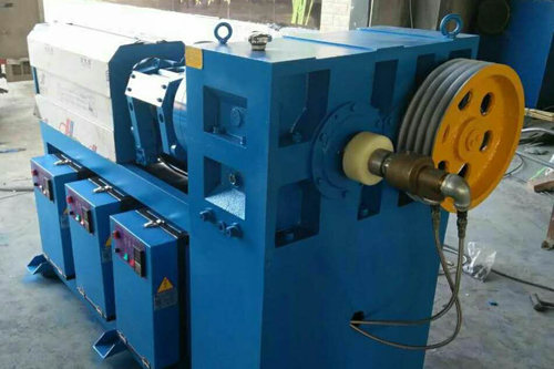
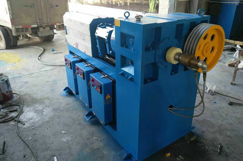
Silicone extruder is tire production process is necessary and required rubber machinery equ...
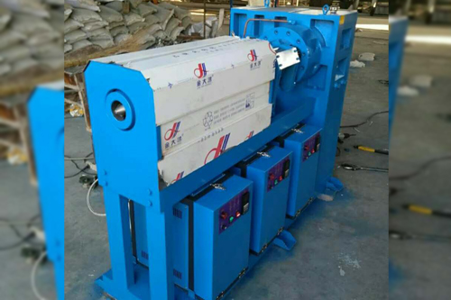 Silica gel extruder
In the rubber machinery industry, the silicon extruder is a more common and more commonly u...
 Use of extruder hea
CONDAT forging lubricants with unique ingredients designed to help create companies in chal...
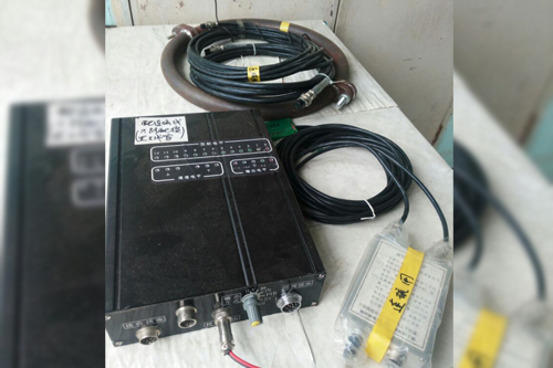
The performance principle of the high performance no-adjustable suspension controller is non-contact, the installation position is at the midpoint of the catenary line, and the combination of the pressure 16MPa.
Device at each end with a transmitter coil and receive coil, according to the cable position is centered in the crosslinking tube, remove the error signal to control the traction, under guarantee the cable in heating period is not clean tube, always in the center position.
Suspension adopts foreign production line technology, the production line is actually used, the technology is advanced.
The import original, new, integrated module, stable performance, adjust the middle point not to drift.
Instruction for use
(xc-12b suspension detector)
The installation
Emission coil:
Transmitter coil are two semicircle metal tubes, internal containing conductive coil, each have the wire leads on both ends of the pipe, respectively with another semicircle tube when installation at both ends of the wire connection, a connection lead no line sequence.
The two semi-circular metal pipes are attached to the synthetic ring, and the hoops are on the hanging tube and fixed.
Before the hoops are fixed, the wire should be connected and put into the metal tube.
Be careful not to break the insulation of the wire in the installation. If damaged, you may be able to insulate yourself with a hot shrink casing or teflon tape.
Receiving coil:
Receiving coil are two pieces of printed coil respectively fixed on the hanging pipe and lower part, close to the hanging pipe as far as possible, but don't contact, keep 1 ~ 5 mm clearance, to prevent the temperature of suspension pipe direct incoming and receiving coil burn out.
When installing, be careful: the flat surface of the printed coil must be aligned with the axis of the suspension tube and parallel to the plumb line.
3, launch box:
If the box is closer to the receiver, it must be installed in a metal box within five meters.
If the distance is more than 5 meters, it can be placed at will.
4, receiving box:
The receiving box is light and small, and can be fixed or suspended near the receiving coil. The installation principle is close to the receiving coil, but avoids the heat source.
As far away from the transmitter coil as possible from the launch box.
5, pay attention to:
(1) the firing coil and the wire for the receiving coil are normal insulated sheath, and be careful not to touch the hot hanging tube so that it is not hot.
(2) transmitter coil and receive coil should be installed in the pipeline suspension period, between installation shoulds not be too close, in order to avoid signal by space straight transmission, both from 1 to 30 m.
The connection
After the suspension detector is installed, five connections are required. They are the connection between the power supply, the output, the transmitter coil, the receiver coil, and the receiver box.
All connections need no tools.
All aircraft are plugged in to the production line.
1, the power supply connection
Meet the power input socket board right side for the socket type XG20 12 core, is the power input port of the whole system, will the machine with the power transformer of 12 core plug into the socket.
Control the output connection
Control the output port in the middle of the panel diagram, which is the output of the machine, provides the test output to the governor (regulator, controller), and is an XG12 two-core socket.
It is fitted with a plug that connects the red and black wires to the red and black line.
The red line is the signal end and the black line is the output zero.
The red line is the positive signal when the cable is in the vertical position.
When the position is biased, the red line outputs a negative signal.
If the user USES the shield wire to connect the output, the shield layer should not be grounded, and the location should be at the governor's end.
3, the launch coil connection
The launch output socket is located at the top of the launcher box and provides a transmitting signal to the launcher coil, which is an XG12 connector.
Plug in the plug of the launcher coil to the socket and spin the buckle (very important!).
It is.
Receiving coil connection
Receiving coil outlet at left, two core for two XG12 type socket, respectively for the connection of the upper and lower receiver coil input, which depend on the side of the red light socket connection "on the" receiving coil, and by the side of the green light socket connection "down" to receive coil.
Connect the plug to the socket by connecting the connecting plug on the suspension tube and the lower side receiving coil.
Turn the buckle (very important!)
It is.
(for some special USES reverse input speed regulator or controller, can also be in the upper and lower switch receiving coil, it implements the signal phase, and does not affect the signal grounding, but may need to trailer after the switch center position to zero.)
The transmitter and receiver are interlinked
The work controls the socket, each of which has an XG16 type 9 socket (see right-hand chart) on the launcher box and receiver box.
Its role is between the transmitting and receiving box, transmit power, signals and control signals, match with this machine has 9 core connection with head on both ends of the connecting cable, connect them and tighten their respective buckle ring (very important!)
Basic debugging
Debugging simplicity: 2 steps
(1) the central standard position of the cable (whether the line diameter, insulation or not) is the central standard of the tube.
(2) the machine is electrically charged, adjusting the knob on the receiving box, and the two red and green leds on the box are extinguished or both gleam at the same time.
-- debugging!